
Home About Us Services Products RF Systems RF Components Filters Antennas NanoCeramic Superconductive Recent Projects Contact Us Updated 21.12.2010 |
RF SYSTEMS COMPONENTS FILTERS ANTENNAS NANO-CERAMICS SUPERCONDUCTIVE SPECTRUM REGULATIONS HTS RF FRONT-END High Temperature Superconductive (HTS) Millimeter Wave Radio Frequency (RF) Front-End. Preliminary results of analysis based on the available factual material and extensive circuit-level and system-level modelling effort, indicated considerable unused potential becoming available after implementation of HTS Integrated Front-End. This system solution is the only possible way for exploiting all advantages of the HTS technology in full scale. Selective component-level applications of HTS films donít produce significant system-level effects. On the contrary, integrated Front-End opens the possibility for considerable simultaneous improvements in several system parameters: sensitivity, EIRP, spectrum efficiency. Depending on the system parameters overall Noise Figure improvement may be expected starting from 2.5dB upwards comparing to conventional system. In practical terms this means possibility of approaching overall Noise Figure around 1 dB (in Ka-band) resulting in significant increases in the system range or coverage area. Spectrum efficiency improvements expected to increase spectrum utilization by 20% and more. This demanding specification for overall system Noise Figure is not achievable with thin-film HTS technology due to additional losses introduced by dielectric substrate and coaxial junctions unavoidable with thin-film HTS. Taking that RF systems typically represent mature technology, with all significant system reserves already reclaimed, and developers working hard for every dB of the system budget, integrated HTS front-end opens attractive perspectives for significant advances in system performance.
By
definition RF Front-End is a combination of the Receiver Input Circuit
and
Low-Noise Amplifier (LNA) integrated into single assembly unit and
located
close to receiving antenna to reduce overall system level of noise
(system
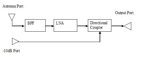
Noise Figure) Block-diagram of the HTS RF Front-End is presented below
in Fig.
1. Basically RF Front-End presents configuration consisting of Low
Noise
Amplifier connected to antenna through passive RF network. RF front-end
has
input port either connected directly to antenna output port or through
short and
low loss cable (waveguide). The output of the RF Front-End is normally
connected to Receiver through a cable or transmission line. Auxiliary
port, for
example -10 dB coupled port may be reserved for additional input signal
depending on the system requirements.  Fig.
1. Block Diagram of HTS RF Front-End Signal
from the Antenna port is passing through the Band Pass Filter (BPF),
and then
to the LNA. Output of the LNA is connected to the The HTF Front-End operates in the 20GHz to 24GHz frequency band. This band is defined by filter pass-band at the levels of 0.15 dB at the edge. Central Frequency is 22 GHz. Corresponding absolute Pass-band is 4 GHz. Relative pass-band is 18%. Performance of HTS band pass filter HTS BPF is instrumental in achieveing low specified Noise Figure. |